When a plastic part does not fit properly, the problem goes far beyond wasted material. Poor dimensional accuracy can lead to assembly issues, product returns, production delays and higher manufacturing costs. That is why understanding plastic injection molding tolerances is essential for developing reliable, high-quality components.
At Atienza & Climent, we know that dimensional precision plays a key role in the performance and competitiveness of any plastic product. By defining the right tolerances, anticipating material shrinkage and validating geometry throughout the process, manufacturers can reduce errors and improve part consistency from the start.
What are plastic part tolerances and GD&T?
Plastic part tolerances define the acceptable variation in the dimensions of a component. In other words, they establish how much a finished part can differ from its nominal design and still function correctly.
In more advanced product development, GD&T for plastic parts helps go beyond basic measurements. Geometric Dimensioning and Tolerancing allows engineers to control not only size, but also form, position, orientation and profile. This is especially important in plastic components used in assemblies, technical products or parts that require repeatable performance.
Using GD&T improves communication between design, tooling, production and quality control teams. It also reduces ambiguity and helps ensure that every critical feature is manufactured according to its function.
Linear tolerances vs geometric tolerances in plastic parts
Traditional linear tolerances define acceptable size variation using values such as ±0.2 mm. While this method is useful, it is often limited when dealing with complex parts or components that need precise alignment.
Geometric tolerances in plastic parts provide a more functional way to control quality. Instead of focusing only on dimensions, they define tolerance zones for specific features. This makes it possible to control characteristics such as flatness, concentricity, perpendicularity or true position.
For plastic parts that must fit, move or seal correctly, geometric tolerances often offer better control than linear tolerances alone.
Key factors that affect tolerances in plastic injection molding
Achieving consistent tolerances in plastic manufacturing depends on several variables. The final dimensional stability of a part is influenced not only by the CAD design, but also by material behaviour, mould design and processing conditions.
Some of the main factors include:
- Plastic material type
- Part geometry and wall thickness
- Mould design and gate location
- Cooling conditions
- Injection parameters
- Surface finish and texture
- End-use environment
Understanding these factors is essential for defining realistic and functional tolerances.
How plastic shrinkage affects dimensional accuracy
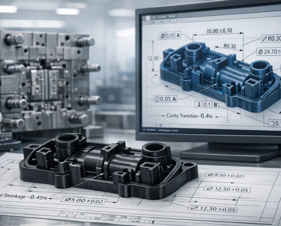
One of the most important issues in plastic injection molding tolerances is plastic part shrinkage. As the polymer cools after injection, it contracts. This change in volume can affect the final dimensions of the part and create deviations from the original CAD model.
Shrinkage varies depending on the material, part design, cooling rate and mould conditions. Semi-crystalline plastics, for example, often show higher shrinkage than amorphous materials. Complex geometries and uneven wall sections can also increase the risk of distortion or dimensional inconsistency.
To improve dimensional accuracy in plastic components, shrinkage must be considered during the design stage. This is typically done by applying compensation in the mould or CAD model so that the final part meets the required specifications after cooling.
How to define tolerances correctly in 3D plastic part design
Tolerances should not be added as an afterthought. In plastic product development, they need to be integrated into the design from the beginning. A 3D model that includes clear dimensions, functional references and GD&T annotations helps prevent misunderstandings later in the process.
Defining tolerances correctly means identifying which features are critical for assembly, sealing, movement or aesthetics, and which areas can allow more variation. This approach supports both manufacturability and cost control, since overly tight tolerances can increase tooling complexity and production costs.
Using GD&T in CAD for plastic parts also improves traceability and creates a more efficient workflow between engineering and production teams.
GD&T for plastic parts in CAD environments
Modern CAD systems allow engineers to add GD&T annotations directly to 3D models. This helps create a more precise technical definition of the part and reduces dependence on ambiguous 2D interpretations.
Applying GD&T for plastic parts in the digital design phase offers several benefits:
- Better communication between departments
- Clear identification of critical features
- Improved dimensional inspection planning
- Reduced risk of manufacturing errors
- Better alignment between design intent and finished part function
This is particularly useful in technical plastic components where small deviations can affect product performance or assembly quality.
The impact of surface texture and finishes on tolerances
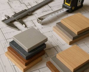
Surface texture is not just an aesthetic decision. In plastic manufacturing, finishes and texturing processes can influence the final dimensions of a part, especially in critical areas.
Deep textures, chemical etching, sandblasting or decorative finishes may alter the surface of the mould and slightly change the dimensions of the plastic component. While these variations may seem minimal, they can still affect fit, movement or contact between parts.
That is why surface texture in plastic parts should always be considered when defining tolerances. Draft angles, part geometry and mould dimensions may need to be adjusted to compensate for the effect of texture on the final component.
Ignoring this relationship can lead to problems that only become visible during assembly or product use.
Quality control and dimensional inspection in plastic components
Defining tolerances is only one part of the process. Verification is essential to confirm that the manufactured part meets design requirements. This is where dimensional inspection in plastic components becomes critical.
Modern metrology systems make it possible to scan a real part and compare it directly with the CAD model. This helps detect deviations, identify trends and validate whether the component falls within specification.
3D metrology for plastic parts offers clear advantages:
- Accurate inspection of complex geometries
- Faster validation processes
- Better defect detection
- Reduced risk of defective parts reaching assembly
- Reliable documentation for quality assurance
This level of inspection is especially valuable in industries with tight quality requirements, recurring production runs or technical assemblies.
Why dimensional accuracy matters in plastic manufacturing
Dimensional precision is directly linked to product quality, performance and cost efficiency. A plastic part that respects the right tolerances is more likely to fit correctly, perform consistently and reduce the need for adjustments or rework.
By combining functional design, realistic tolerances, shrinkage compensation and dimensional validation, manufacturers can improve product reliability and reduce production waste. In competitive markets, this level of control can make a major difference.
At Atienza & Climent, we apply technical knowledge, industrial experience and a practical approach to help ensure that every plastic part meets both functional and production requirements.
Frequently asked questions about plastic part tolerances
Geometric tolerances define the acceptable variation zones in features such as form, orientation and location. In plastic parts, the GD&T system makes it possible to specify these directly in the CAD design for injection moulding, improving precision and communication between design and manufacturing.
Plastic shrinkage during cooling reduces its volume, which can alter final dimensions. To prevent this, shrinkage compensation is applied in the design stage, adjusting the mould dimensions so that the final part meets specifications.
Textures can slightly modify dimensions, especially in critical areas. That is why surface finish and texture must be considered when defining tolerances and validating parts, ensuring that aesthetics do not compromise functionality.
Dimensional control through 3D metrology makes it possible to verify each part precisely. The real geometry is scanned and compared with the CAD model, detecting deviations that could affect performance.